
Concrete on Top. Polystyrene Underneath.
New steel beams were about to bear on foam. Our GPR scan found a hidden waffle pod slab inside a 320 mm reinforced floor, just in time.
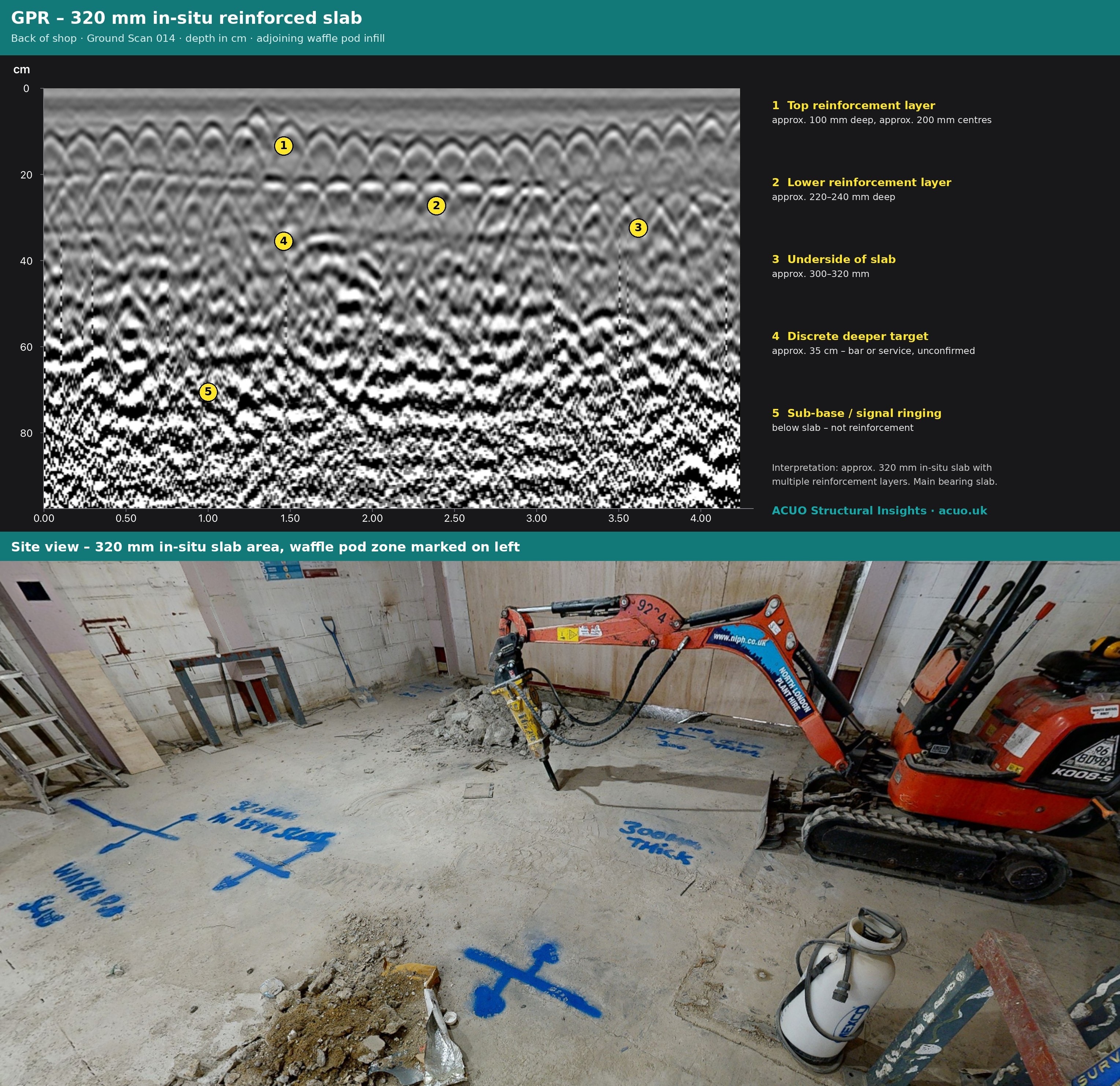
How a Saturday GPR scan stopped new steelwork landing on foam.
The brief
A contractor was refitting a ground-floor retail unit in Central London. The structural engineer had specified new steel beams to carry a mezzanine, with pad bearings sitting directly on the existing concrete floor slab. The slab was assumed to be solid in-situ reinforced concrete throughout.
Before the steelwork arrived on site, the contractor asked us to scan the floor to confirm rebar positions and slab depth. A Saturday morning slot. Straightforward, they thought.
The good news
The back half of the shop scanned exactly as expected. Two layers of reinforcement, top mat at approximately 100 mm, lower mat at 220–240 mm, slab soffit at 300–320 mm. A solid 320 mm in-situ reinforced concrete slab — more than capable of carrying the proposed pad loads.
The plot twist
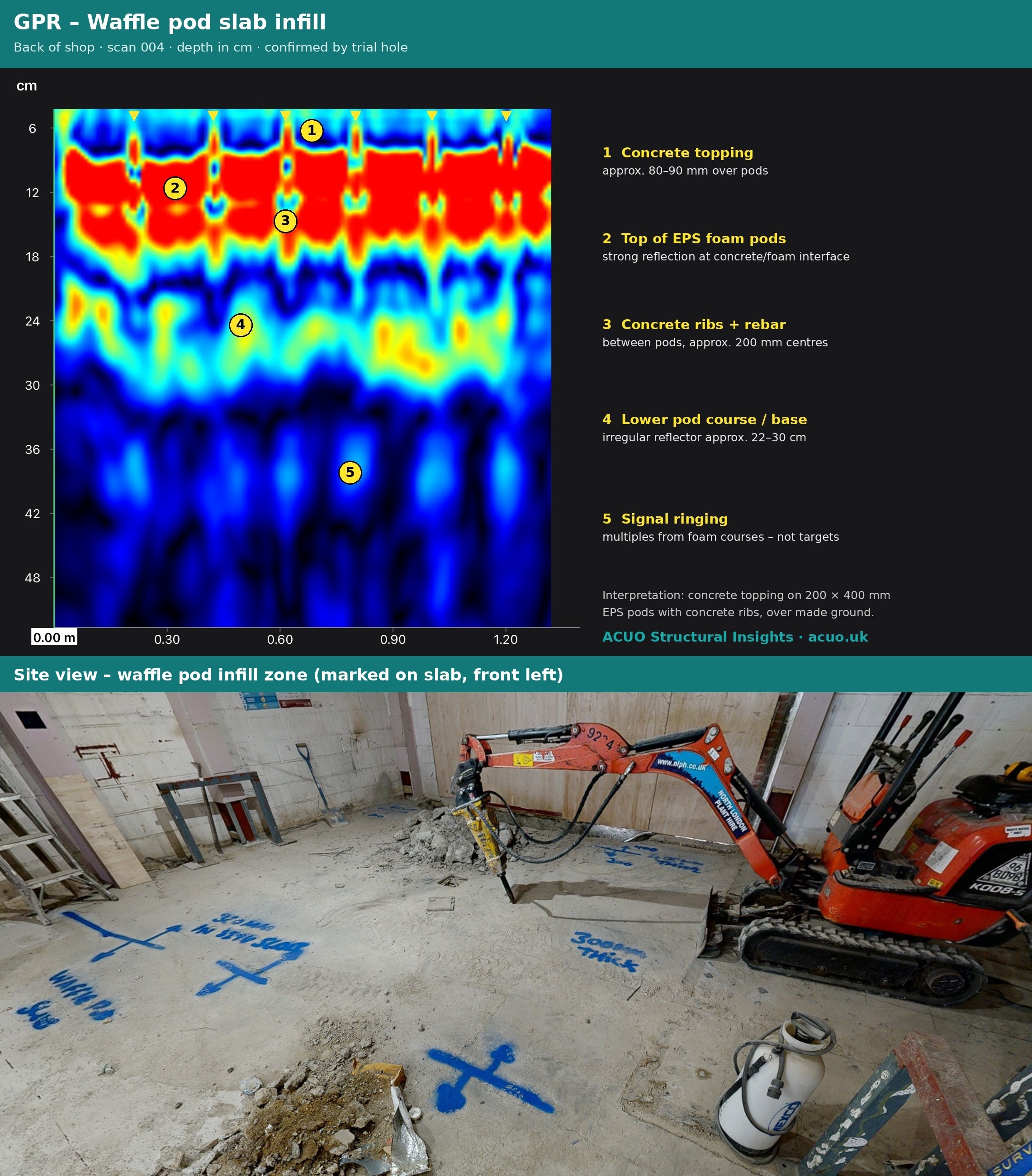
The front half of the shop told a different story. The GPR signal changed completely — a strong, shallow reflection at around 80–90 mm, then a chaotic zone of multiples and ringing below it. No clean lower reinforcement layer. No clear slab soffit.
We recognised the signature immediately: EPS foam pods. The front section of the floor was a waffle pod slab — a concrete topping over expanded polystyrene infill blocks, with concrete ribs running between the pods. The topping was approximately 80–90 mm thick. The pods sat on made ground.
A trial hole confirmed it. Beneath the concrete surface: polystyrene.
Why it mattered
The proposed pad bearing locations were in the waffle pod zone. A steel beam bearing on 80–90 mm of concrete over foam would have been inadequate — the load path simply wasn't there. The structural engineer needed to know before the steelwork was fabricated, not after it arrived on site.
The scan gave the engineer exactly what he needed: the boundary between the two slab types, marked on the floor and documented in the report. Pad positions were redesigned to bear on the solid in-situ zone. The mezzanine went ahead without delay.
The bottom line
A floor that looks uniform at the surface can contain two completely different structural systems. GPR found the boundary in a morning. Redesigning the steelwork took a day. Discovering it after installation would have taken considerably longer.
Concrete scanning in London
ACUO Structural Insights provides GPR concrete scanning, 3D slab surveys and pre-coring clearance for contractors, engineers and fit-out teams across London, Kent, Essex and the South East.
For full details on what the service covers, visit our concrete scanning service page. For a broader look at what GPR can detect in a slab, see our article on what GPR can actually see in concrete.
Explore Topics
Written by
Gary Stringer
Founder of ACUO Structural Insights and GPR NDT Civil Engineer with over 20 years of experience in non-destructive testing, structural investigation and subsurface survey.


